Breaking AES128 with Multi-Bit DPA
This post is about how I attempted to implement Paul Kocher’s well known Differential Power Analysis (DPA) attack by attacking AES128. The attack didn’t work out initially and I had to use my creativity to rediscover a variation of the attack, namely Multi-Bit DPA, which has already been known for years. Ultimately, I managed to implement a DPA attack that can recover the encryption key with nothing but the ciphertext, power traces of the encryption device and a few hours of time.
Background
After reading all these papers that managed to successfully attack widely used algorithms, I decided that I also wanted to take a closer look at attacks on algorithms from a hardware perspective. The timing was very convenient since I was also expected to conduct a project as part of my studies.
But first of all: what even is DPA? DPA is an attack that uses a correlation between power consumption and data in order to recover the key that is being used by a cryptographic algorithm.
It achieves this by using a property of well-designed S-boxes. If you were to guess the value of an input or output bit without actually knowing the input or output of the S-box, you would end up being correct in roughly half of all cases. However, if you know the value on the other end, you can guess the value with a higher accuracy. For the AES S-boxes you would be able to guess the other value with certainty since the S-boxes are invertible. But this is not the case for all S-boxes. DES, for example, uses S-boxes which map a 6 bit input to a 4 bit output. As a result knowing the output would not allow you to recover the input with certainty.
The attack guesses part of the roundkey and simulates a section of the encryption process which also involves the S-boxes in order to determine whether a specific bit is set or not. It then uses this bit to separate the recorded power traces into two sets and calculates the difference between the average of these two sets. If the guess was correct then we will witness a spike in the resulting differential trace. If the guess was incorrect then we are effectively calculating the difference between two randomly picked sets and the differential trace should not exhibit any spikes. Guessing the wrong keybyte also means guessing the wrong S-box input or output, hence any bits derived from this S-box would be correct in half of all cases.
But why are these bits causing spikes in the power consumption? This happens because there is a correlation between the power consumption of a digital circuit and the number of bits switching per clock period. As more bits switch, a higher power consumption will be recorded. The following image demonstrates this:
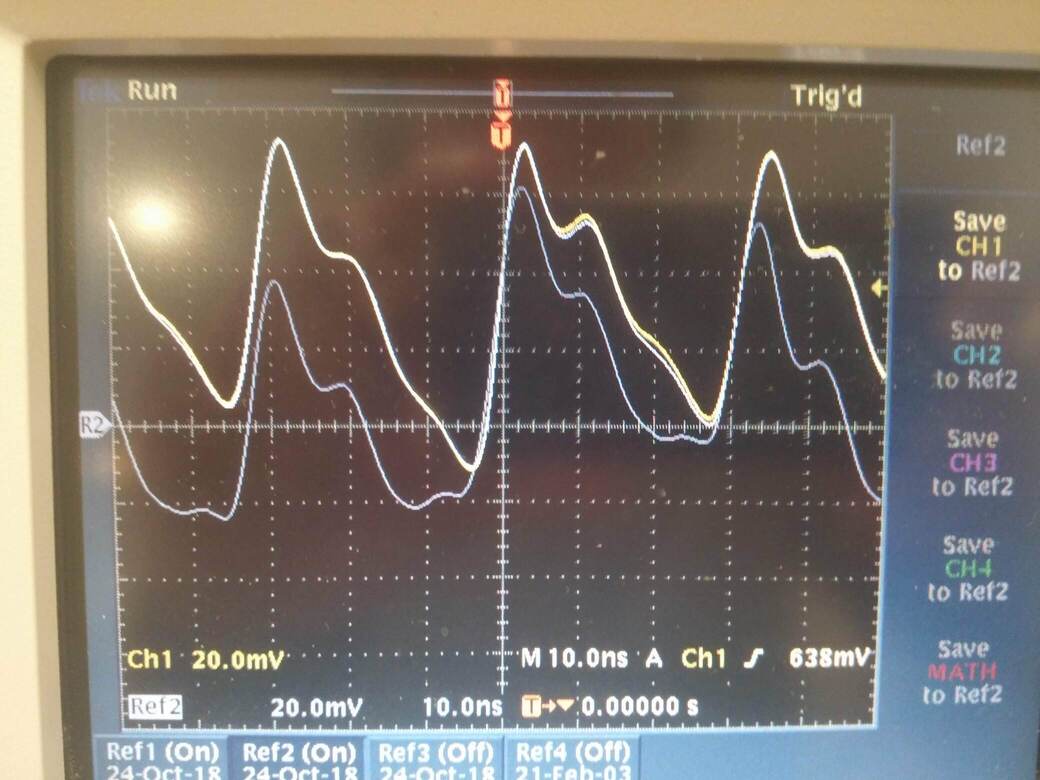 The yellow line is a power trace of a MCU constantly XORing a register with the value 255, while the gray line is the same MCU effectively running a busy wait.
The formula at the heart of Single-Bit DPA is as follows:
\[\Delta_D[j] = \frac {\sum_{i=1}^{m} D(C_i,b,K_s)T_i[j]} {\sum_{i=1}^{m} D(C_i,b,K_s)} - \frac {\sum_{i=1}^{m} (1 - D(C_i,b,K_s))T_i[j]} {\sum_{i=1}^{m} (1 - D(C_i,b,K_s))}\]\(m\): Number of traces
\(C_i\): Current ciphertext
\(b\): Bit to compute
\(K_s\): Keyguess
\(D\): Function that computes value of bit b
\(\Delta_D[j]\): Differential trace sample \(j\)
\(T_i[j]\): Power trace sample \(j\)
Note that the formula only calculates a single sample point and needs to be repeated for all \(j\).
So much for the theoretical background, let’s get started with the actual project.
Setting up an Encryption System
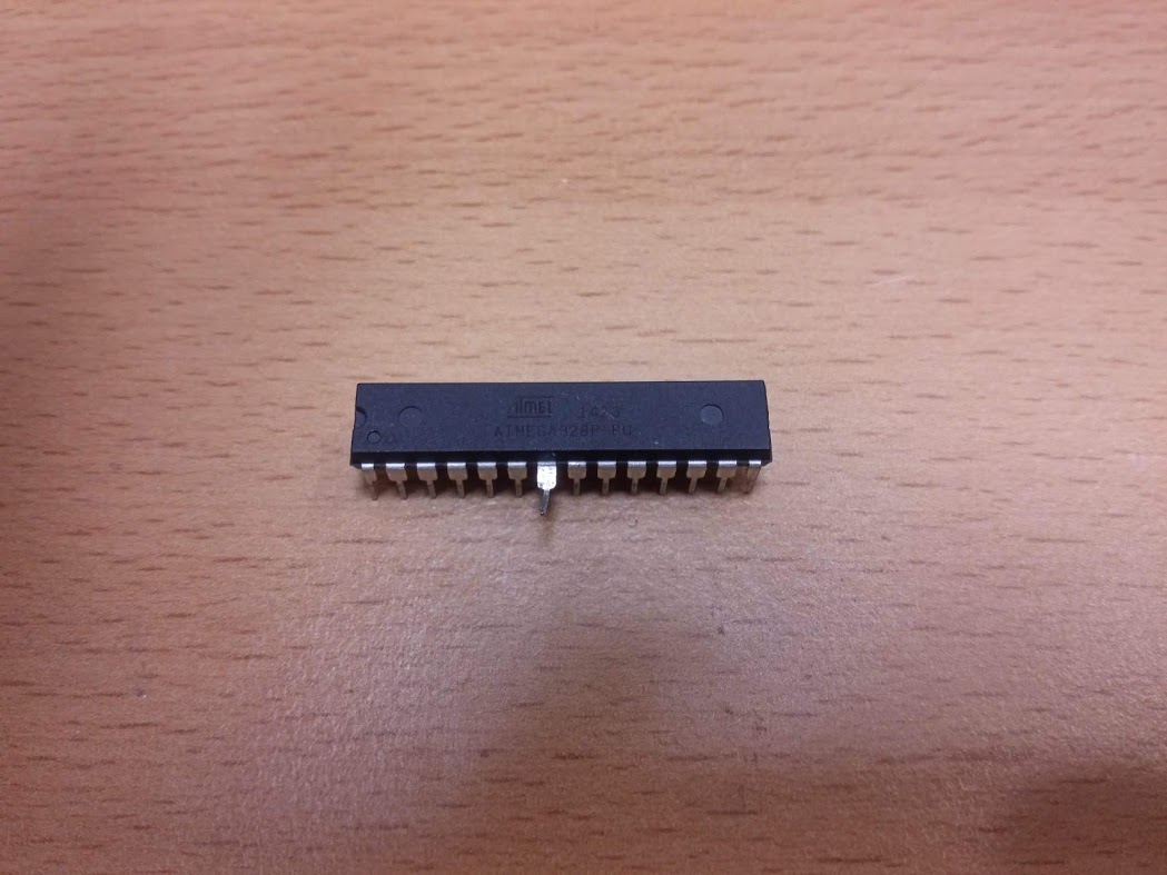
No attack without a Device under Attack. I chose the Arduino Uno since it’s cheap and uses an ATmega328P to execute its programs. This microcontroller has a remarkably low clock frequency of 16MHz, which will come in useful for the next phase of the project. A low clock frequency enables us to capture the traces with cheaper equipment. If we wanted to capture power traces from a device with a clock frequency in the GHz range, we would need significantly more expensive measurement equipment.
The heart of the program running on the device is an assembly implementation of AES128: http://point-at-infinity.org/avraes/.
This implementation was adjusted to conform to the ABI used by GCC.
I grabbed 16 bytes from /dev/urandom and hardcoded them as the key for our system.
#define KEY_MATERIAL "c1e5ec7b1a30e0da98d34ff07030fe65"
Finally we add a bit of code to tell the Arduino to read data over USB, encrypt it and send it back. I’m not going to explain the code any further but I’ll link the Github repository at the end of the article.
Capturing the Data
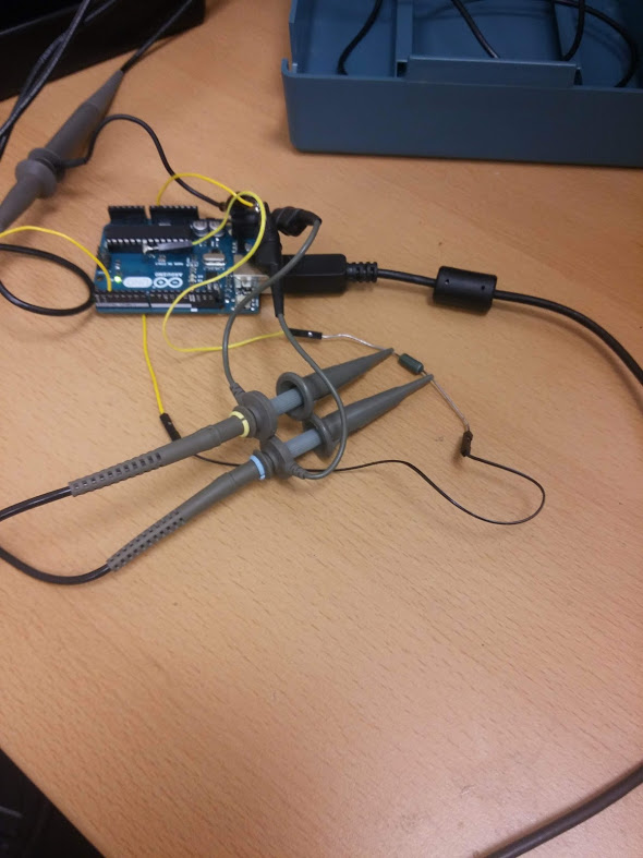
Now that we’ve got a fully functional system to attack, let’s look into how we would best go about recovering its power traces. This requires messing with the hardware. A common approach to capture power traces is to insert a shunt resistor and capture the voltage differential across it. The difference in the voltages allows us to calculate how much current is currently flowing into our processor. This calculation is essentially a multiplication by a constant factor, so it’s meaningless for our correlation and we can simply ignore it. We can simply conduct the attack by using the voltage differential rather than the current flowing through the supply pin.
In order to insert the shunt resistor, I had to bend the pin that the ATmega328P uses for its supply voltage out of the package and solder a wire to the VDD contact on the board.
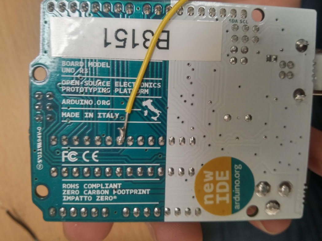
It should be noted that the ATmega328P doesn’t actually need the VDD pin to run properly. There’s also a voltage supply for the analogue parts and this supply is capable of fully powering the microcontroller on its own. This means that we can choose an arbitrarily high resistance for our resistor. Testing revealed that a higher resistance resulted in a bigger voltage differential in our traces and hence, a resistance of 10M Ohm was chosen.
Let’s take a closer look at the device that ought to capture the traces. We’re using a Tektronix TDS3034B oscilloscope at a sampling rate of 1GS/s and with a bandwidth of 300MHz. Two channels are used to capture the voltage differential. The device is capable of storing up to 10 000 sample points.
Encrypting a single block with our algorithm takes about 2500 cycles. This leaves us with 4 cycles per clock period if we wanted to capture the full encryption. However, this isn’t necessary. We are only interested in the last round. This allows us to reduce the number of cycles that we need to capture to roughly 160, hence we may use a sampling frequency of 1GS/s.
I modified the firmware to raise a pin as the device is encrypting data, a busy pin. This pin is used in order to determine when to start measuring.
Once the data has been captured by the oscilloscope, we use a serial interface in order to download the data and configure the scope for the acquisition of another trace. The process of downloading the data is the bottleneck in the capture. Therefore I made an effort at optimising it by using the internal format used by the oscilloscope and using a custom parser to convert it to a CSV file.
We capture around 10 000 traces with each trace being the result of an encryption. The corresponding ciphertext is captured too of course. This whole process takes almost three hours.
Implementing the Attack
Implementing the attack is fairly straightforward. We use pandas to parse the CSV files and then proceed to store the data in numpy arrays.
The heart of the attack is this simple loop:
    limit = 8 if MULTI_BIT else 1

    for current_measurement in range(parser.n):
      for i in range(limit):
        if(selector_function(parser.ct[current_measurement], guess, n, i)):
            sel_1 += parser.measurements[current_measurement]
            sel_1_cnt += 1
        else:
            sel_0 += parser.measurements[current_measurement]
            sel_0_cnt += 1
    current_samples.append(sel_1 / sel_1_cnt - sel_0 / sel_0_cnt)
\(n\) specifies the current roundkey byte that we are attacking. \(guess\) ranges from 0 to 255 and this code fragment is executed for each possible value. \(i\) is the bit of the keybyte that we attack and \(parser.n\) is the number of traces that were captured. Numpy allows us to simply divide all samples of a trace by a scalar value and to easily calculate the difference between two sets of traces. This is why we don’t have to iterate through every sample of a trace.
You might have noticed that I didn’t explain what the Multi-Bit in Multi-Bit DPA means. I thought that this would be best explained by the previous code sample. As you can see, we simply iterate through every possible target bit rather than only using a single bit to calculate our differential traces. A fairly trivial modification which, as you will see later on, bears a significant impact.
One part that might still be a little unclear is how the selector function works.
def selector_function(ciphertext, guess, n, i):
  pre_add_roundkey = ciphertext[n] ^ guess
  #no need to reverse shift rows, sub bytes doesn't care about order
  pre_sbox = inverse_sbox[pre_add_roundkey]

  return bool(pre_sbox & 2**i)
As you can see we start off by inverting the \(AddRoundKey\) step of AES, proceeded by inversing the S-box lookup. \(ShiftRows\) merely shuffles the bytes of the state around and hence has no impact on the values occurring the state. It can be ignored for our purposes.
Executing this code presents us with a set of differential traces. One trace for every guess and every attacked byte. For our final step we need to sort the differential traces for every byte based on the size of their peak. The guess corresponding to the highest peak for a given byte should then be the correct guess.
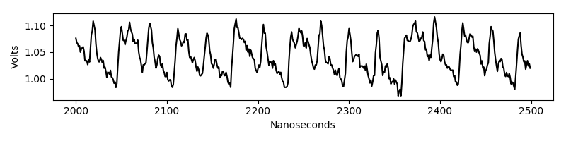
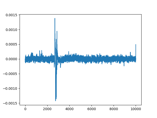
The following is a differential trace corresponding to the correct guess:
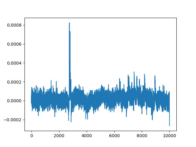
And this is a differential trace for an incorrect guess.
Notice that we still see a spike albeit a lower one.
This peak is known as a ghost peak.
Ghost peaks prevented us from successfully recovering the key with Single-Bit DPA.
Once we captured all the bytes that make up the final round key, we can simply invert the key schedule in order to recover the initial key that was used.
def round_transform(word_inp, round_num):
    word = word_inp[:]
    word = word[1:] + word[:1]
    word = bytearray(map(lambda x : sbox[x], word))
    word[0] ^= rcon[round_num]

    return word

def xor_bytes(a, b):
    return bytearray(z ^ x for (z, x) in zip(a, b))

def get_old_rk(current_rk, num):
    old_words = current_rk[:]
    for x in range(2, -1, -1):
        old_words[4*(x+1):4*(x+2)] = xor_bytes(old_words[4*(x+1):4*(x+2)], old_words[4*x:4*(x+1)])
    old_words[:4] = xor_bytes(old_words[:4], round_transform(old_words[-4:], num))

    return old_words
Results
The original Single-Bit DPA algorithm fails to recover the original key with 15 000 traces. We would likely require significantly more traces but sadly, this was becoming too time consuming and I never figured the amount out.
The following graph shows statistics for attacking a single byte of the roundkey. Original refers to Single-Bit DPA and modified to Multi-Bit.
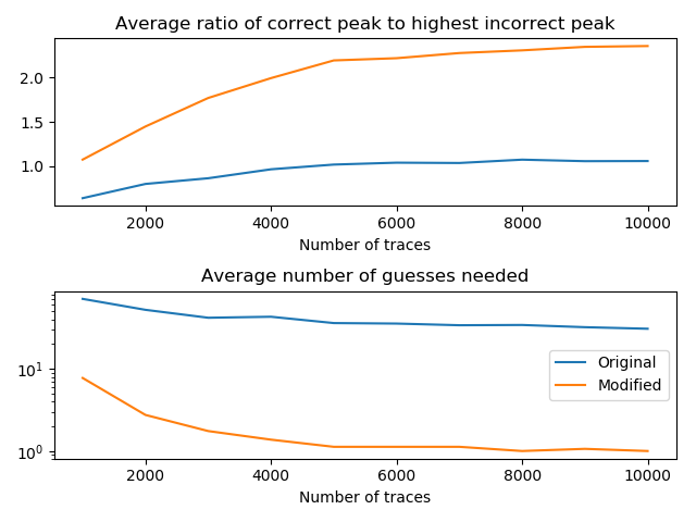
Capturing 10 000 traces takes about 3 hours while performing the attack itself requires 140 minutes. The Single-Bit variant completes in about 24 minutes.
The final roundkey that we recover is b1785b045afd4ccb79ef0ca0895065c5. Passing this to our key schedule inversion script returns the original AES key:
$ ./recover_initial_key.py b1785b045afd4ccb79ef0ca0895065c5
Initial RK found:
c1e5ec7b1a30e0da98d34ff07030fe65
External Links
Kocher’s paper: https://www.paulkocher.com/doc/DifferentialPowerAnalysis.pdf
The original AES implementation: http://point-at-infinity.org/avraes/
The modified version with C bindings: https://github.com/3553x/FAST-AES-AVR
The custom parser for the Tektronix internal file format: https://github.com/3553x/Tektronix-File-Converter
The repository with the rest of the source code: https://github.com/3553x/Power-Analysis